Technos launches a new version of its true shape nesting software.
Astra S-Nesting supports import of parts from the DXF format, automatic true shape nesting, quick manual correction of layouts, automatic assignment and manual correction of the cutting path, as well as export of CNC data into ISO G-code and ESSI formats.
About Astra S-Nesting software
Astra S-Nesting is intended for optimizing the true shape nesting process for metal,
fabric, leather, plywood, glass, stone and other plate materials.
All the features of Astra S-Nesting were specifically designed for quick fulfillment of true shape nesting tasks. The simple and intuitive tools of the program enable you to do the following:
- Import parts from any CAD application in the DXF format
- Automatically nest parts of arbitrary shape on specified sheets
- Quickly and accurately edit layouts
- Automatically calculate and manually edit cutting paths
- Print reports
- Export CNC data into ISO G-code and ESSI formats for CNC machines (laser cutters, plasma cutters, etc).
How to start working with Astra S-Nesting software?
In short, you need to do the following:
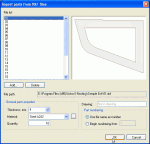
1. Import parts for nesting. Parts are imported from the DXF (Drawing Exchange File) format. To start the import process, run the Import command from the File menu. Use the Import parts dialog to add files to be imported and enter the parts’ properties. If the necessary material in not on the list, click the “…” button to the right of the Material field to open the material library. The program also allows you to disable manual entry and configure automatic import of part properties from a DXF file: drawing number, part number, material name and thickness.
2. Add sheets for nesting. Sheets can be added using the Add plates command from the Nesting menu. Once you run the command, a dialog will open that will enable you to enter the dimensions of the sheet, its thickness and quantity. If the number of sheets is unlimited, you don’t need to enter this value.
3. Perform automatic true shape nesting. To start order nesting,
use the Start nesting command from Nesting menu. To complete automatic nesting, switch to the Layouts tab of the order form to view the calculation result.
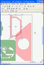
4. Manually correct nesting layouts. If you need to manually correct nesting layouts, switch to the Layouts tab of the order form, select the layout from the list and use the Open command from the context menu. The layout editing mode enables you to move and rotate parts using the mouse and special precise positioning commands.
5. Print reports. The program enables you to print the following reports: the drawing of the current layout, thumbnails of layouts selected on the list, specification of order parts, specification of order layouts.
6. Export of nesting results into DXF. To export the list of layouts into the DXF format, select them on the Layouts tab of the order window and use the Export command from the context menu.
Editing of layouts
Open one or several layouts for editing. To open several layouts at the same time, select them from the list while holding Ctrl or Shift and use the Open command from the context menu. To change the location of opened layout windows, use the commands from the Window menu.
The following commands are available in the layout editing mode:
Group selection of parts. All commands and operations on a layout affect one part or a group of selected parts only. You can select a group of parts using the mouse while holding down the Shift key or using a selection box. A selection box will appear around the selected parts. The Select all command from the Edit menu selects all the parts on the current layout.
Moving of selected parts is carried out with the help of the selection box. Parts can be grabbed by the center of the selection box and moved to the edges of adjacent parts or the edge of the plate (with snapping). If a part is grabbed by the body, it can be moved arbitrarily (without snapping). Clicking any of the corner markers on the selection box will move the part to a stop above, below, to the right or left, depending on marker clicked.
Parts can also be moved using the arrow keys on your keyboard (up, down, left, right). The value of the movement step is selected from the Movement step dropdown list on the Edit toolbox.
Rotation of selected parts is carried out in one of the following ways:
- Arbitrary rotation can be done using the mouse and rotation markers on the selection box. Press the left mouse button over any marker and move the cursor to rotate the part.
- Rotation by a fixed angle is carried out with the help of the Rotate… command in the Edit menu. The Rotation angle is selected from the dropdown list on the Edit toolbar.
Special functions provide quick and precise editing of nesting layouts:
- Paralleling of part edges.
- Working with the clipboard – Copy and Paste parts on the layout.
- Undo/Redo commands and operations that enable you to quickly go back to any previous state of the layout.
- Scaling allows you to view the layout and its fragments with any level of zooming.
A detailed description of these and other features can be found in the help section of Astra R-Nesting software and the user manual supplied with the program. The demo version of the program is available on the official website:
http://www.techno-sys.com/astra-shape-nesting-software.asp
Enjoy your work with Astra S-Nesting software!


No Comments Found